Skip to content

7 Tips for 480V to 13.8kV Step Up Transformer Specs

Selecting a 480v To 13.8kv Step-Up Power Transformer Specs requires more than matching two voltage numbers. The transformer must fit the complete electrical system, including load demand, fault levels, grounding, protection, and installation conditions. A 480 V industrial source can feed a 13.8 kV distribution network, but small specification errors may create severe voltage stress, nuisance trips, or unsafe overheating.

Transformer specialist Thomas A. Prevost offers a useful design principle: “A transformer specification is a system document, not merely a nameplate.” That statement deserves attention. Engineers should verify the required kVA rating, frequency, phase arrangement, impedance, insulation level, BIL, cooling method, and tap range. The secondary winding also needs a clearly defined neutral and grounding method. Do not leave that detail vague.

Field experience adds another lesson. A transformer may carry the calculated load, yet fail expectations when motors start, harmonics rise, or ambient temperature reaches 40°C. Short-circuit withstand capability must match the available fault current at both voltage levels. Outdoor units may need weatherproof enclosures, sealed bushings, corrosion protection, and suitable sound limits. Indoor installations require space for ventilation, inspection, and cable bending.

The numbers can look correct.

Still, assumptions deserve review.

This guide presents seven practical tips for developing reliable 480v To 13.8kv Step-Up Power Transformer Specs. It also highlights common gaps in preliminary schedules, including unclear tap positions, incomplete grounding data, and unrealistic future-load allowances. Good specifications are precise, but they should remain honest about uncertainty. That balance supports safer purchasing, easier commissioning, and more dependable long-term operation.
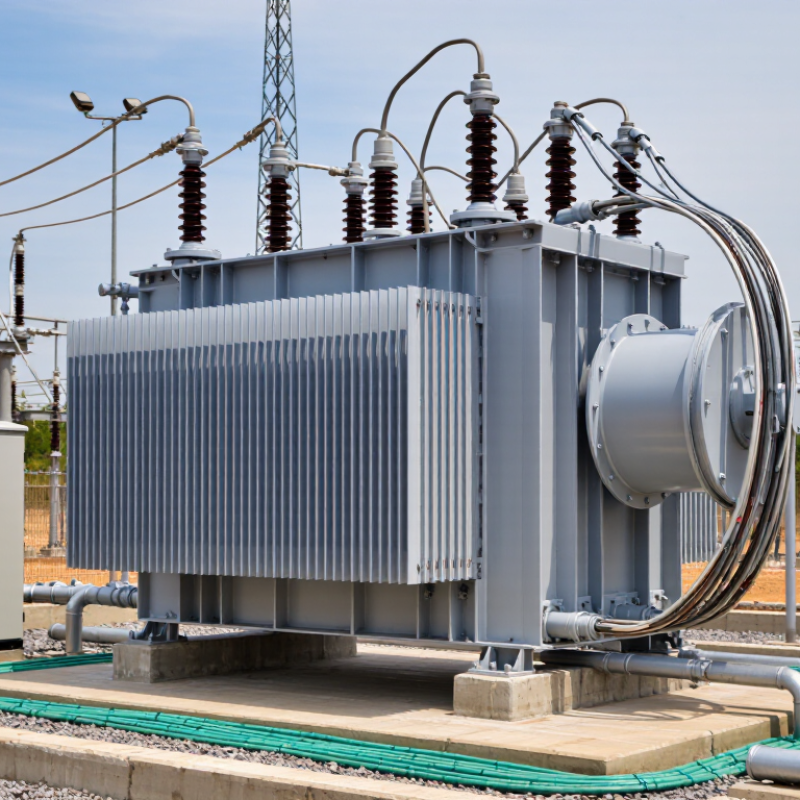
7 Tips for 480V to 13.8kV Step Up Transformer Specs

Define the 480 V–13.8 kV Ratio, Phase, Frequency, and kVA Rating

7 Tips for 480V to 13.8kV Step Up Transformer Specs

1

Tip 1: Define the voltage ratio clearly. A 480 V to 13.8 kV transformer has a nominal ratio of 28.75:1. State whether voltages are line-to-line or line-to-neutral.

2

Tip 2: Confirm the phase system. A three-phase unit is typical for industrial distribution.

3

Tip 3: Specify frequency, usually 60 Hz in North America. EIA electricity data identifies 60 Hz as the standard grid frequency there, but project sites still require verification.

4

Tip 4: Size the kVA rating from measured demand, not guesswork. For a 1,000 kVA, three-phase transformer, rated current is about 1,202 A at 480 V and 41.8 A at 13.8 kV. Add motor starting, future expansion, and ambient temperature.

5

Tip 5: Select taps and impedance carefully. A 2.5% tap step may help control voltage, while impedance affects fault current and motor starting.

6

Tip 6: Check insulation and winding temperature ratings against IEEE C57.12.00 or IEC 60076 requirements. DOE technical analyses separate no-load and load losses, showing why efficiency depends on both energized time and loading.

7

Tip 7: Record enclosure, cooling, grounding, and short-circuit withstand requirements. DOE transformer rulemaking reports evaluate lifetime energy losses, not only purchase cost. That matters. A lightly loaded transformer can waste energy continuously through core losses. I would still challenge a convenient 1,000 kVA selection without twelve months of load data. Missing field measurements can make a clean specification misleading.

Calculate Full-Load Currents Using 480 V and 13.8 kV System Data

7 Tips for 480V to 13.8kV Step Up Transformer Specs

For a three-phase transformer, calculate full-load current with I = kVA × 1,000 ÷ (1.732 × voltage). A 500 kVA unit draws about 601 amperes at 480 V. On the 13.8 kV side, it draws approximately 20.9 amperes. The current falls sharply as voltage rises.

Use line-to-line voltage consistently. Do not mix phase voltage with a three-phase formula. For single-phase equipment, use I = kVA × 1,000 ÷ voltage. This simple error can distort cable sizing, fuse selection, and thermal checks. Confirm the transformer rating before calculating.

Tip 1: Check the nameplate kVA, primary voltage, secondary voltage, phase, and frequency. Tip 2: Include efficiency and power factor when estimating operating input current. Full-load current is a rating reference, not always the measured value. Tip 3: Review impedance, tap range, insulation level, and short-circuit withstand requirements. A 13.8 kV winding needs suitable insulation coordination and clearances.

Keep a calculator nearby. I recheck the 480 V result because small unit mistakes create large conductor changes. Also verify whether 13.8 kV means nominal system voltage or actual operating voltage. Real installations may operate slightly above or below nominal values. Local engineering rules and site conditions still control the final specification.

480 V to 13.8 kV Step-Up Transformer: Full-Load Current Comparison

This chart compares calculated three-phase full-load currents at the 480 V low-voltage side and the 13.8 kV high-voltage side for common transformer ratings. Current is calculated using I = kVA × 1,000 ÷ (√3 × line-to-line voltage).

Assumption: The values represent balanced three-phase transformer systems using nameplate apparent power. Actual operating current may vary with loading, system voltage, and operating conditions.

Specify 15 kV-Class Insulation With 95 kV Basic Impulse Level

7 Tips for 480V to 13.8kV Step Up Transformer Specs

Specify 15 kV-class insulation with a 95 kV Basic Impulse Level (BIL). IEEE Std C57.12.00-2020 identifies 95 kV BIL as a suitable insulation level for many 15 kV-class applications. This rating helps the 13.8 kV winding withstand lightning and switching surges. It does not replace surge arresters, proper grounding, or adequate clearances.

41.8
The 13.8 kV winding carries about 41.8 amperes at 1 MVA.
1,203
The 480 V winding carries nearly 1,203 amperes.

Small details matter.

Tip 1

State BIL by winding. Write “13.8 kV high-voltage winding, 15 kV class, 95 kV BIL,” rather than listing only a nameplate voltage.

Tip 2

Request impulse-test documentation using IEEE Std C57.12.90. Confirm whether the requirement covers routine, design, or type testing. Those terms are not interchangeable.

Tip 3

Check insulation coordination against IEEE Std C62.22 and the installed surge arrester rating. A 95 kV BIL specification can still perform poorly with long cable runs, sharp bends, or weak grounding.

Tip 4

Define the neutral treatment, winding connection, and altitude correction. For a 13.8 kV system, the phase-to-ground voltage is approximately 7.97 kV. Designers sometimes overlook this value. That is worth reviewing.

A technically correct specification may still be incomplete if enclosure clearances, termination stress control, and field acceptance tests remain vague.

Set Impedance, Tap Range, and Fault Withstand for System Coordination

7 Tips for 480V to 13.8kV Step Up Transformer Specs

A 480V-to-13.8kV transformer needs more than a voltage ratio. Specify frequency, phase arrangement, cooling, insulation levels, and continuous load current. IEEE C57.12.00-2021 establishes general requirements for power transformers, while IEEE C57.12.90-2021 defines important test methods. These standards support comparable factory data. They do not replace site studies.

Impedance controls fault current and voltage regulation. A 5% impedance transformer could produce roughly 20 times rated current under an ideal three-phase fault. Real systems deliver less, because cables, utility sources, and motors add impedance. Request positive-sequence and zero-sequence values, not only one nameplate percentage. IEEE 242 recommends coordination based on calculated fault current, relay curves, and equipment withstand ratings. Tap ranges also need practical limits. A ±5% range may be inadequate when a long 480V feeder causes voltage drop. However, excessive taps can complicate protection settings and maintenance.

Fault withstand deserves direct attention. Specify the short-circuit duration, commonly two seconds when required by the study, and verify thermal and mechanical withstand through IEEE test procedures. The 13.8kV side should state BIL, grounding method, and breaker clearing time. ANSI C84.1 voltage limits help frame acceptable operating conditions, but local utility rules remain decisive. I prefer reviewing a one-line diagram before selecting taps. On paper, 7.5% impedance looks reasonable. In the field, it may create unacceptable motor starting voltage. That detail is easy to miss.

Verify Cooling, Efficiency Above 98%, Grounding, and IEEE C57.12.00 Compliance

For a 480V-to-13.8kV step-up transformer, efficiency must be verified at the actual operating load. A claim above 98% is incomplete without no-load and load-loss data. Request certified test results, temperature-rise values, and the guaranteed loss curve. The U.S. Department of Energy’s 2024 distribution-transformer rule projects about 3.6 quadrillion Btu in energy savings over 30 years, showing why small loss reductions matter across large fleets. Field conditions still differ from laboratory ratings.

Cooling deserves equal attention. Confirm whether the design uses ONAN or ONAF cooling, and check the rated temperature rise at the site’s ambient temperature. Blocked radiators, dust, and frequent overloads can quietly shorten insulation life. The IEEE C57.12.00 standard establishes general requirements for liquid-immersed transformers, including insulation, temperature, and dielectric performance. However, compliance should include routine and design-test documentation, not only a statement on the datasheet. That is easy to overlook.

Grounding requires a system study. Confirm the winding connection, neutral availability, ground-fault current, and any neutral grounding resistor before selecting protection settings. A grounded-wye high-voltage winding may be appropriate, but it is not automatically correct. Verify clearances, bushing insulation levels, surge protection, and the site grounding grid. One practical weakness remains: many specifications emphasize voltage ratio while treating grounding as installation detail. That can create expensive revisions later.